

- China Sales: +86-769 81585810
- Email: sales@jactonindustry.com
- Email: jactonjack@gmail.com
- Whatsapp: +86 135 3283 0851
Home » Product Detail
Products
 |
Selection Guide of JTS Series Bevel Gear Screw Jacks
Model: JTS25-JTS200
Brand Name: Jacton
Order Quantity: MOQ 1pc Acceptable
Product Origin: Guangdong, China
Assembly Drawing: 3D (stp, step, model, igs), 2D (dwg, dxf), PDF
Delivery Time: 10-15 Working Days After Payment
Payment Methods: T/T, PayPal, Western Union, MoneyGram
Transportation Modes: Air Freight, Sea Freight
Shipment Port: Shenzhen, Guangzhou, Hongkong
Packages: Strongest Exporting Plywood Cases

Description:
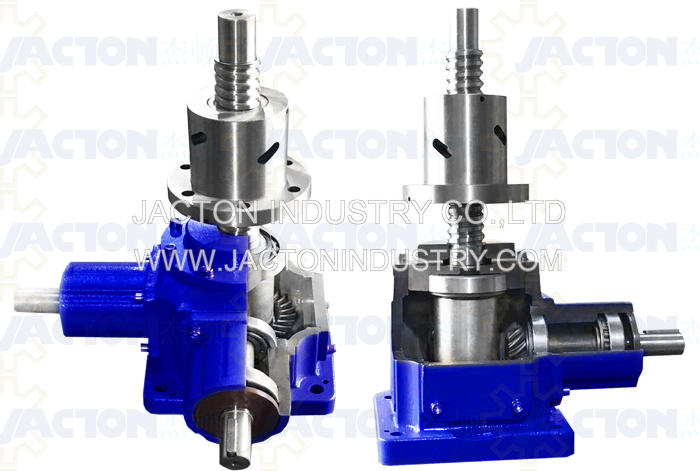
Selection Guide of JTS Series Bevel Gear Screw Jacks
Find out more about how to correctly select a complete part number of JTS Series Bevel Gear Screw Jacks?According to the following sample part number with corresponding additional informaton about JTS Series Bevel Gear Screw Jacks designs, configurations, end conditions, worm shaft codes and accessories.
Example Order Code: JTS50 - US - 500 - H - II - C - PP
JTS25, JTS50, JTS100, JTS150, JTS200
Note: click your required model web pages directly, there are specifications tables and assembly drawings for your reference.
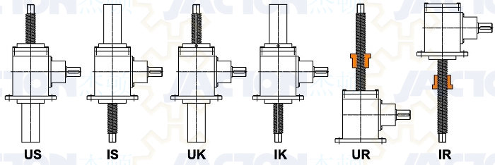
2. Configuration and Designs
US = Upright Translating Screw Design; IS = Inverted Translating Screw Design
UK = Upright Keyed Screw Design; IK = Inverted Keyed Screw Design
UR = Upright Rotating Screw Design; IR = Inverted Rotating Screw Design
Note: The screw of a translating screw design jack must be attached to the load (guided) which prevents the screw from rotating. Add linear guides, rails or rolls are recommended.
Note: If your application involves a load which is unattached, unguided or the load is free to rotate and not translate, then a keyed screw design jack are required to prevent trapezoidal screw rotation (not recommended).
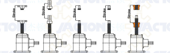
3. Travel Length
There are no standard travel length and all JTS series bevel gear screw jacks travel length are built with customers required.
Note: If compressive loads, must consider the trapezoidal screw permissible buckling load.
4. Gear Ratios
Each JTS series bevel gear screw jacks in two bevel gear ratios, H: high speed, L: slow speed
| Models | H - High Ratio | Travel Length (mm), Per Turn of Input Shaft | L - Slow Ratio | Travel Length (mm), Per Turn of Input Shaft |
| JTS25 | 1:1 | 6 | 2:1 | 3 |
| JTS50 | 1:1 | 7 | 2:1 | 3.5 |
| JTS100 | 1:1 | 12 | 2:1 | 6 |
| JTS150 | 1:1 | 12 | 2:1 | 6 |
| JTS200 | 1:1 | 12 | 2:1 | 6 |
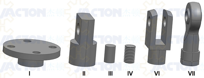
5. Screw End Conditions
Standard trapezoidal screw end conditions include I=top plate (fixing flange), II=clevis end (pivot bearing end), III=plain end, IV=threaded end, VI=fork end, VII=rod end, and no screw end with full threads lead screw.
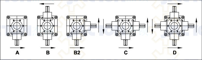
6. Input Shaft Types
A: Single input shaft drive
B: Inline double shafts drive
B2: Right angle double shafts drive
C: Three shafts (T) drive
D: Four shafts drive
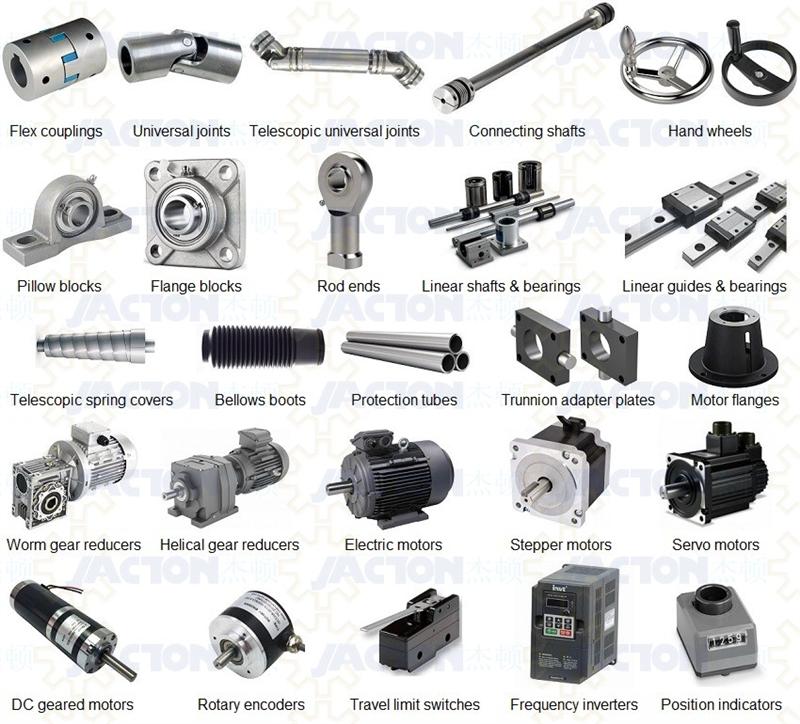
7. Additional Accessories
JTS Series Bevel Gear Screw Jacks with a comprehensive range of accessories like FC=Flex couplings, UJ=Universal joints, TUJ=Telescopic universal joints, CS=Connecting shafts, HW=Hand wheels, PB=Pillow blocks, FB=Flange blocks, RE=Rod ends, LSB=Linear shafts and bearings, LGB=Linear guides and bearings, TSC=Telescopic spring covers, BB=Bellows boot, PP=Protection tubes, TAP=Trunnion adapter plates, TMB=Trunnion mounting brackets, MF=Motor flanges, WGR=Worm gear speed reducers, HGR=Helical gear reducers, EM=Single phase or three phase induction motors, STM=Stepper motors, SEM=Servo motors, DCGM=DC geared motors, REN=Rotary encoders, LS=Travel limit switches, FIN=Frequency inverters, PIN=Position indicators, SN=Stop nuts, TN=Travel nuts, SNU=Safety nuts.
Warning:
1. Input RPM should not exceed 1500 RPM.
2. Never exceed the JTS Series Bevel Gear Screw Jacks static and dynamic capacity.
3. Never exceed the power listed in our JTS Series Bevel Gear Screw Jacks specification tables. If the maximum power recommendation is exceeded, reduce the speed, use a larger capacity bevel gear screw jacks, choose another bevel gear screw jacks ratio, or consider a more efficient screw jack type such as a ball screw bevel gear screw jacks.
Products List
Contact Us

JACTON INDUSTRY CO.,LTD.
Building 2, No. 1,
Dongcheng Road, Chang An,
Dongguan, Guangdong, China.
Post Code: 523880
Tel: +86 769 8158 5810
Fax: +86 769 8158 5852
Email: sales@jactonindustry.com
Email: jactonjack@gmail.com
Whatsapp: +86 13532830851
Wechat: +86 13532830851
Skype: jactonjack
TradeManager: jactonjack
Online QQ: 2512868631
Website: www.jactonindustry.com
Products
- Screw Jack with Handwheel
- Screw Jack with Motor
- Cubic Machine Screw Jacks
- Cubic Ball Screw Jacks
- Single Face Machine Screw Jacks
- Single Face Ball Screw Jacks
- Single Face Stainless Steel Screw Jack
- Bevel Gear Machine Screw Jacks
- Bevel Gear Ball Screw Jacks
- Super High Speed Screw Jacks
- Electric Cylinder Actuators
- Parallel Electric Linear Actuators
- Inline Electric Linear Actuators
- Electro-Mechanical Linear Actuators
- Compact Cubic Bevel Gearboxes
- Bevel-T Right Angle Gearboxes
- Aluminum Housing Gearboxes
- Servo Spiral Bevel Gearboxes
- Multiple Screw Jack Lifting Systems
Supports
JACTON INDUSTRY CO.,LTD.
Building 2, No. 1,
Dongcheng Road,
Dongguan, Guangdong, China
Post Code: 523880
Phone:+86 769 8158 5810
Email:sales@jactonindustry.com
Building 2, No. 1,
Dongcheng Road,
Dongguan, Guangdong, China
Post Code: 523880
Phone:+86 769 8158 5810
Email:sales@jactonindustry.com
English Site |
Chinese Site |
 |
 |
JACTON INDUSTRY CO.,LTD | VAT No. 9144190007026567X3 | Website Legal Notice | Privacy Policy | Terms and Conditions
Copyright © 2018 JACTON INDUSTRY CO.,LTD All Rights Reserved | Design By:Jacton | Youtube | Facebook | LinkedIn | Twitter | Pinterest | Google+ | Sitemap